Engineering and Quality

Engineering applied to manufacturing. Quality throughout every stage.

We develop industrial components from drawings, models, samples or operating data, integrating engineering, simulation, manufacturing, inspection and technical documentation.

Talk to our engineering team
projects developed
More than 250

For different equipment and industrial applications.

on the in-house quality team
3 professionals

Monitoring materials, processes, testing and records.

per component
Up to 1,500 kg

Subject to review of material, geometry, process and technical requirements.

Engineering connected to production

Technical decisions aligned with manufacturing, inspection and assembly.

At Itametais, engineering works directly with the teams responsible for manufacturing. This integration makes it possible to assess not only component geometry, but also material, casting process, machining, welded joints, assembly interfaces and the controls required by the project. Engineering may be provided as an independent technical service or in support of components manufactured by Itametais.

  • Customer
  • Patternmaking
  • Casting
  • Machining
  • Special welding
  • Quality control
  • Assembly
  • Final inspection

Development from drawings or samples

From understanding the application to reconstructing functional geometry.

The work may involve new component development, made-to-drawing manufacturing, reconstruction, resizing, material or process adaptation, improvement of existing designs and component restoration.

When the original drawing is unavailable, the team may survey the component and its interfaces. With used parts, wear is assessed so deformation or material loss is not reproduced as an original design feature. Reconstructing functional geometry depends on the available references, operating data and technical information.

The development and any proposed changes to geometry, material or process are submitted to the customer for approval before manufacturing.

Development may begin with

  • 2D technical drawing
  • 3D model
  • New sample
  • Used or worn component
  • Survey on the equipment
  • Operating data
  • Assembly requirements
  • Failure history

Technical visits

When necessary and within the project scope, Itametais may conduct technical visits.

Dimensional survey • Equipment assessment • Failure analysis • Assembly follow-up • Inspection • Sample collection • Interface identification • Survey of operating conditions

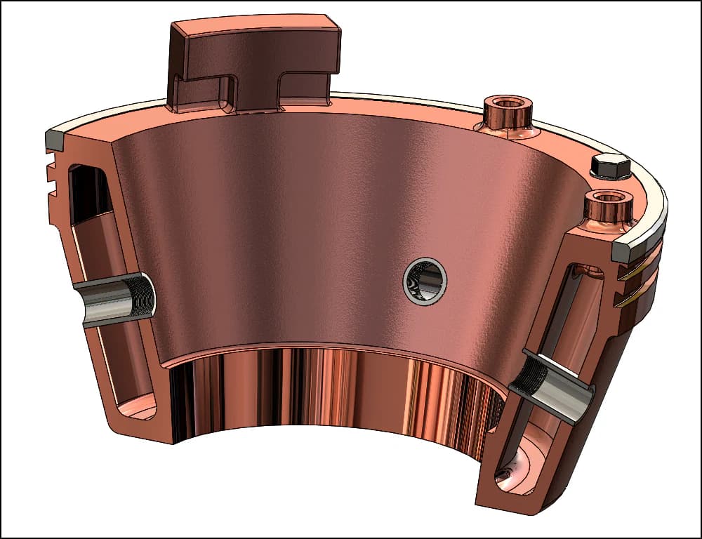
3D CAD model of an industrial copper component developed by Itametais engineering
3D design of a copper component.
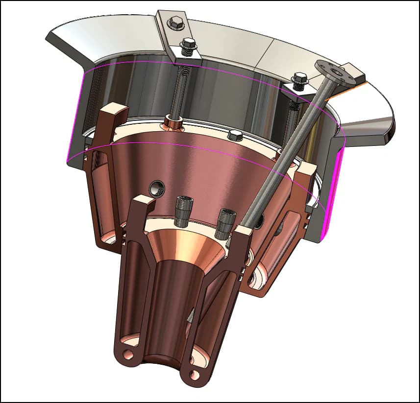
Sectioned 3D CAD model of a water-cooled industrial copper assembly
Internal detailing and assembly interfaces.
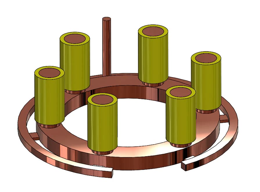
3D CAD model of a circular copper assembly with cylindrical elements
Geometry and positioning defined in the CAD environment.
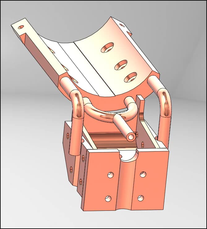
3D CAD model of a water-cooled component with copper channels and piping
Cooling channel and connection design.

Integrated workflow

Five stages, from application to release.

Engineering, production and quality share information and criteria throughout development and manufacturing.

  1. Technical assessment of the application01

    Understanding the application

    Review of the drawing, sample, equipment, operating conditions, interfaces, history and customer requirements.

  2. Component development and modeling02

    Development and simulation

    Modeling, reverse engineering, calculations and analyses to assess geometry, material, operation and critical points.

  3. Manufacturing process definition03

    Process definition

    Planning of casting, machining, welding, assembly, controls and supply condition.

  4. Integrated component manufacturing04

    Integrated manufacturing

    Coordinated execution across patternmaking, casting, machining, special welding and other production stages.

  5. Final inspection and release05

    Inspection and release

    Dimensional checks, tests, records, traceability and documentation in accordance with the contracted scope.

Quality throughout

With an in-house team of three professionals, Quality Control monitors materials, processes, dimensions, testing and records throughout manufacturing.

Raw material receiving • Alloy preparation • Melting and molding • Shakeout and finishing • Machining and welding • Assembly • Final inspection • Documentation and dispatch

Modeling, calculations and simulation

Analysis to support decisions before and during manufacturing.

Based on the input data and project objectives, engineering can compare alternatives, identify critical points, assess cooling circuits and support process definition or improvement.

Digital development

3D modeling • 2D technical drawings • Reverse engineering

Casting simulation

Filling analysis • Solidification analysis • Porosity and shrinkage assessment • Feeding and riser analysis

Thermal and fluid flow

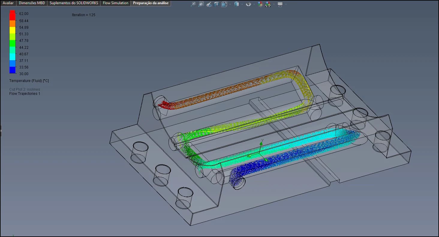
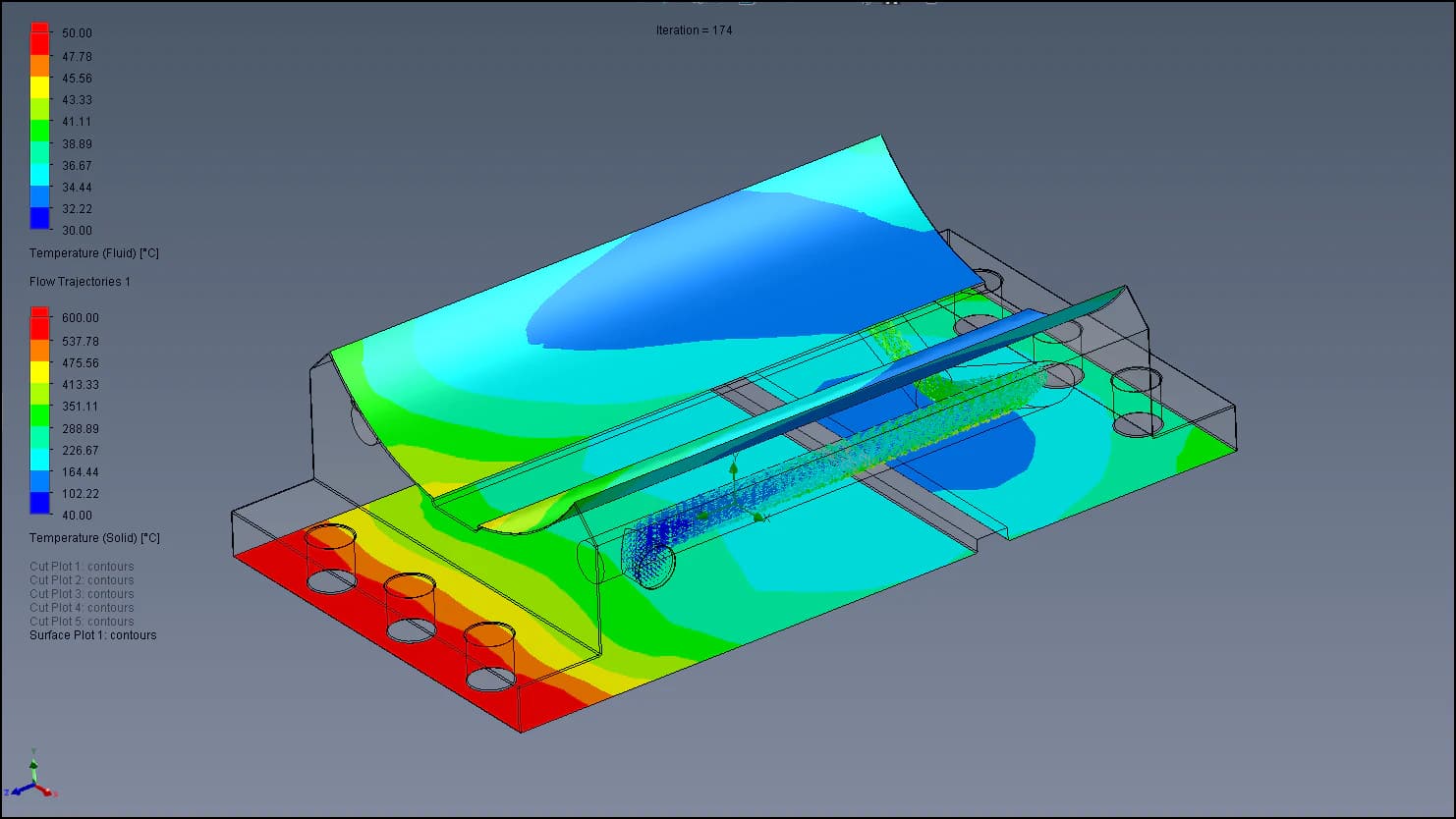
Thermal analysis • Fluid flow and cooling circuits • Flow rate, pressure and pressure drop • Fluid velocity • Heat transfer and temperature distribution

Structural and electrical

Finite element analysis • Stress and deformation • Current • Electrical resistance

Results support decisions and reduce development uncertainty, but depend on assumptions, input data and adopted criteria. Simulation does not guarantee operation or replace applicable physical testing and inspection.

Technology resources

The team uses tools integrated into its technical workflow. 3D printing may support prototypes, geometry validation, foundry patterns, fixtures, gauges and technical presentations to customers.

SolidWorks • SolidWorks Flow Simulation • Inspire Cast 2025 • AutoCAD • PowerMill • 3D printing

Dimensional surveys

Surveys use instruments suited to the component geometry, tolerance and access conditions.

Calipers • Micrometers • Bore gauges • Height gauges • Dial indicators • Measurement arm • Coordinate measuring machine

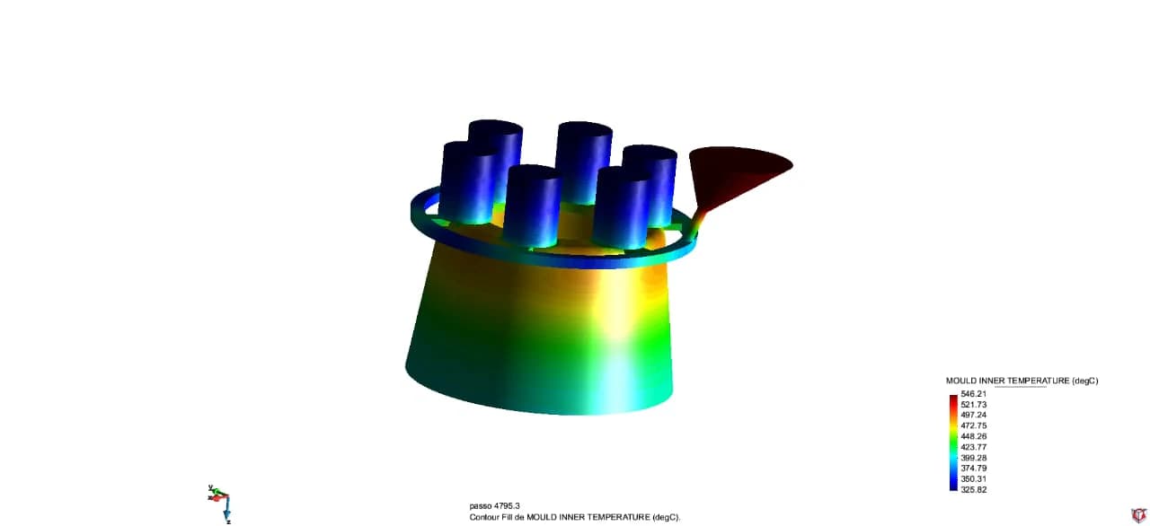
Casting simulation showing temperature distribution in an industrial assembly
Predicted thermal distribution during casting.
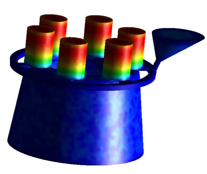
Thermal simulation result for the casting process of an industrial component
Temperature analysis applied to the feeding system.
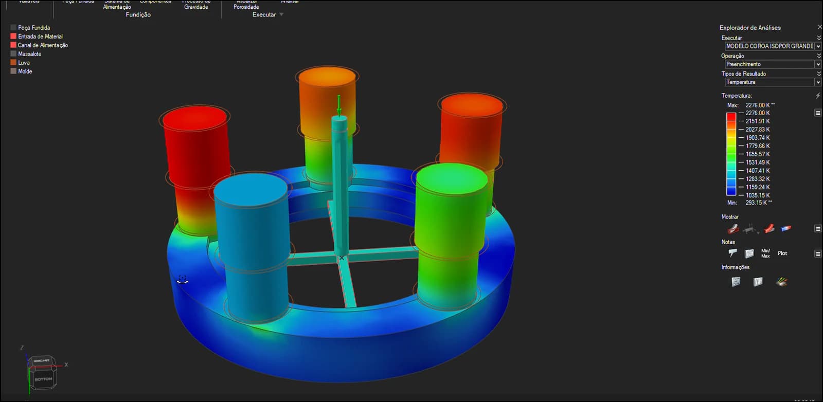
Inspire Cast simulation with a component temperature map
Thermal assessment of filling and solidification.
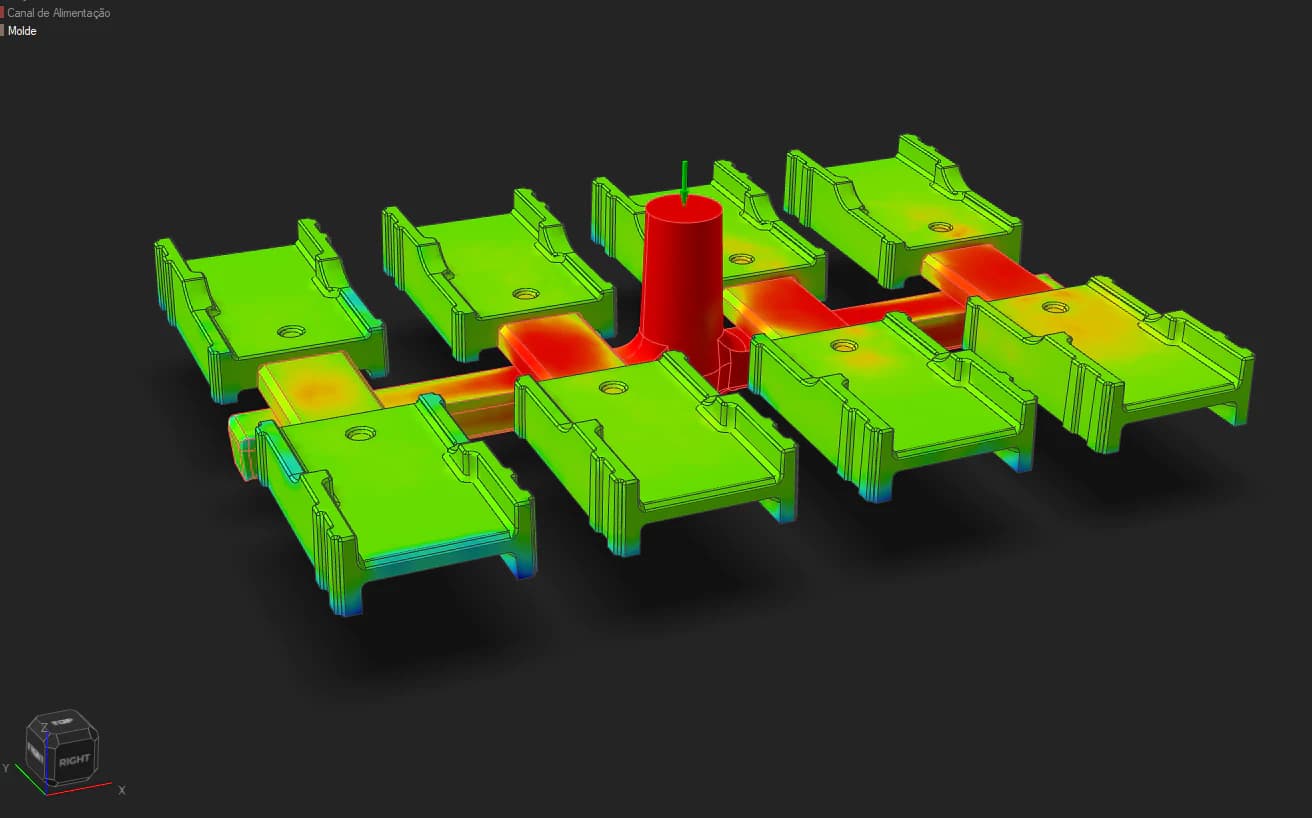
Casting simulation of multiple parts with a shared feeding system
Thermal behavior study of the cast assembly.
Thermodynamic simulation of flow and temperature in cooling channels
Fluid trajectories through the cooling channels.
Temperature and flow map from a thermodynamic simulation of a cooled component
Thermal distribution in the component and internal circuit.

Quality Control

In-house controls and independent verification.

The inspection and test plan is defined according to the drawing, applicable standards, order requirements and the scope agreed with the customer. Controls may be performed in-house or by external laboratories and companies depending on the method, acceptance criteria and need for independent verification.

Chemical composition monitoring

Chemical composition is monitored during the process using an in-house spectrometer.

Independent report

When required for documentation and release, the formal chemical composition report is issued by an independent third-party laboratory, reinforcing impartial verification.

Available testing and inspection

The selected checks reflect the component function and technical requirements defined for the supply.

Materials and properties

Chemical analysis • Hardness testing • Tensile testing • Metallography • Electrical conductivity • Micro-ohm resistance measurement

Non-destructive testing

Ultrasonic testing • Liquid penetrant testing • Radiographic testing

Dimensional inspection

Dimensions and geometry • Tolerances • Hole position • Concentricity • Alignment • Assembly interfaces

Water-cooled components

Hydrostatic testing • Leak testing • Flow testing • Circuit mapping

Assembly

Pre-assembly • Fit-up tests • Verification between components

As applicable to the drawing, standard and contracted requirements.

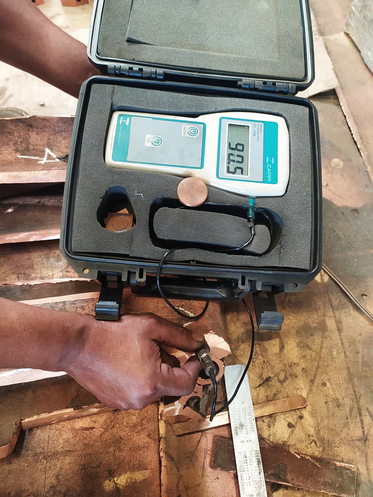
Electrical conductivity test on a copper sample using a conductivity meter
Electrical conductivity measurement on copper.
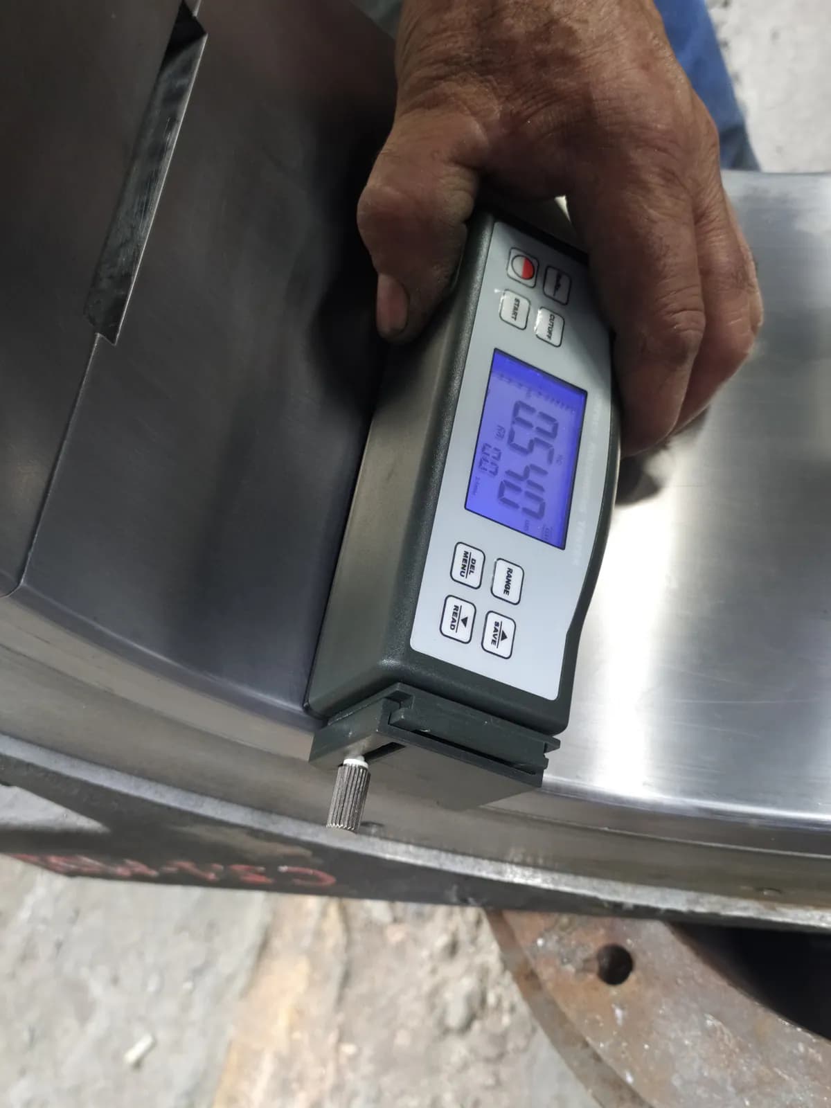
Surface roughness test on a machined metal component using a portable roughness tester
Machined surface roughness verification.
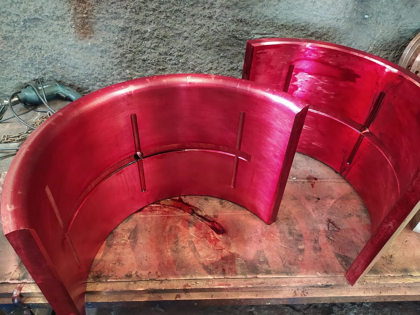
Liquid penetrant test with red penetrant applied to a copper component
Liquid penetrant application stage.
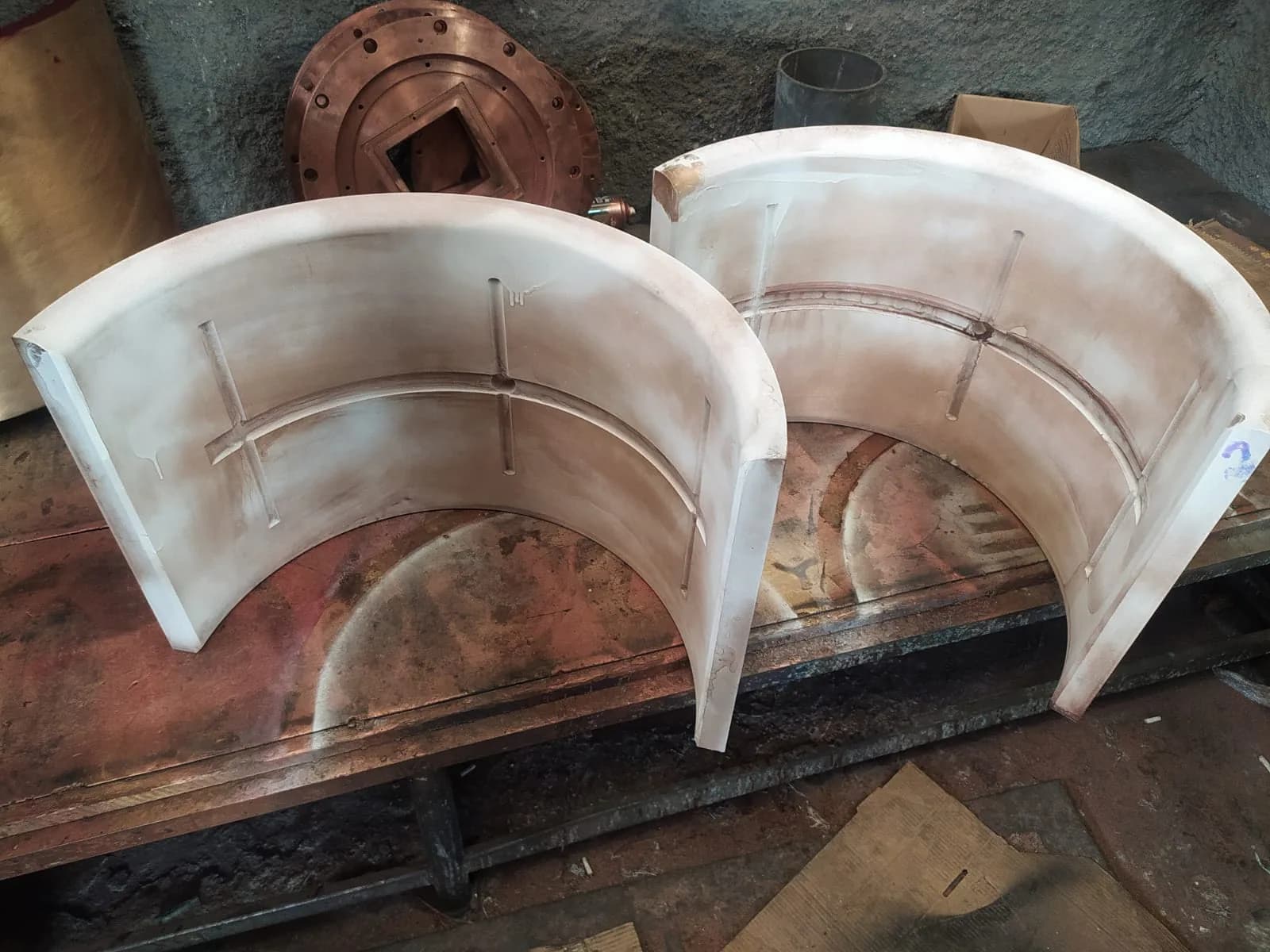
Liquid penetrant test after white developer application on a copper component
Developer stage for discontinuity inspection.

Technical responsibility and records

Technical criteria that support final release.

The contracted scope defines the controls, documents, witness points and responsibilities applicable to each supply.

Technical responsibility

Itametais has legally qualified engineering and CREA registration. When included in the scope, work may include an ART technical responsibility record, calculation memorandum, technical report or signed engineering opinion issued by a legally qualified professional.

Confidentiality

Customer drawings, models, files and technical information are handled confidentially, with formal procedures and agreements when applicable.

Standards and qualifications

Manufacturing and inspection may follow SAE, ASTM, ABNT, DIN or other standards specified by the customer. Non-destructive testing personnel or companies hold the applicable formal qualification, including SNQC/ABENDI where relevant to the contracted method.

Instrument control

Measuring instruments are calibration-controlled and have valid certificates under the applicable procedures.

Welding

Subject to material, process, product and contract, work may involve WPS, procedure qualification, qualified welders, execution records and weld inspection.

Nonconformities and customer inspection

When a nonconformity is identified, RNC records, root-cause analysis, Ishikawa, 5 Whys, action plans and 8D may be used, followed by effectiveness checks. Under the contract, the customer or an inspection company may witness manufacturing stages and tests and review documents before dispatch.

Traceability according to scope

Identification by heat number, production order, component code and marking links the component to applicable manufacturing, inspection and release records.

Raw material • Alloy and heat • Mold and casting • Machining • Welding • Testing • Final inspection • Dispatch

Technical documentation

According to the contracted scope, records are controlled and retained in line with the requirements applicable to the supply.

2D drawings • 3D models • Simulation, dimensional and photographic reports • Inspection and test plan • Material and test certificates • ART and calculation memoranda • Technical reports and engineering opinions • Data book

Applications across industrial sectors

Steelmaking • Mining • Ferroalloys • Base metals • Cement • Pulp and paper • Sugar and ethanol • Energy • Hydropower • Industrial maintenance • Special machinery and equipment

Technical assessment

Shall we assess your project?

Send the drawing, sample or application information. Our team can assess the geometry, material, manufacturing process, simulations and required controls.

Useful information: drawing, 3D model, sample, material, dimensions, operating conditions, equipment, failure history, required tests and quantity.